Missing decoupling capacitor on a drone PCB lets switching-regulator ripple push the 3.3V rail to 4.34V, killing a BMM150 magnetometer under battery power.
Key Takeaways
SY8113IADC switching regulator produces ripple pushing the 3.3V rail from 2.74V to 4.34V under battery; BMM150 is rated only to 3.6V.
Multimeter shows a steady 3.3V; only an oscilloscope reveals the ripple. Bulk readings mask high-frequency noise entirely.
Decoupling capacitors absorb HF switching noise locally at the IC’s supply pins; omitting one lets spikes exceed the part’s absolute maximum rating.
The BMI270 IMU on the same noisy rail survived, suggesting per-IC tolerance varies even when supply specs look identical on paper.
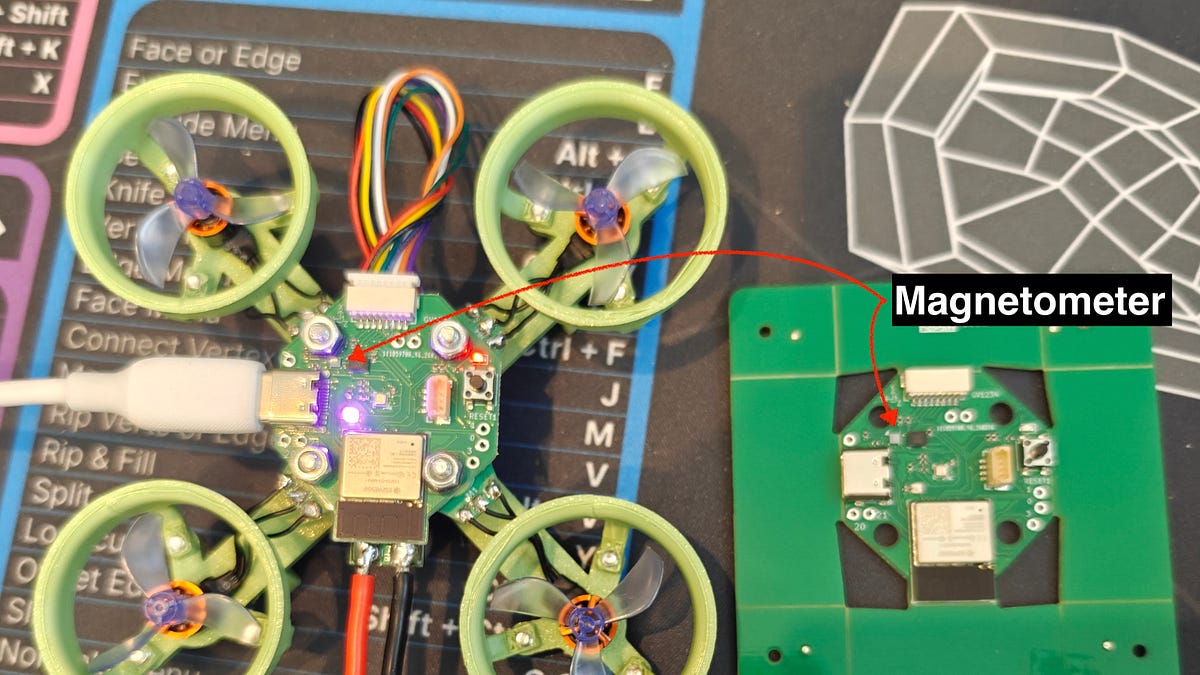
Workaround: Qwiic external magnetometer bypasses the bad rail, losing hardware IMU-sync but restoring yaw tracking.
Hacker News Comment Review
Commenters question whether the ~50MHz waveform is regulator switching at all; the frequency is far above typical buck converters, pointing instead toward inadvertent oscillation or 6-meter-band RF pickup from drone radio gear.
Several commenters argue the 1.5V peak-to-peak ripple (2.74V-4.34V) indicates insufficient bulk capacitance on the regulator output, a separate problem upstream of where a small decoupling cap would help.
The “place decoupling caps as close to the IC as possible” rule gets pushback: on 4/6-layer boards with a solid power plane, cap placement matters far less than commonly taught in hobby tutorials.
Notable Comments
@oakwhiz: Flagged a missed experiment: dead-bug soldering a capacitor to nearby vias would have confirmed whether the cap alone fixes the BMM150 failure.
@WarmWash: Suggests a ferrite bead on the SMPS output, or adding 100nF and 10nF caps directly across the switcher output, as practical rework options before replacing the magnetometer.